Product Description
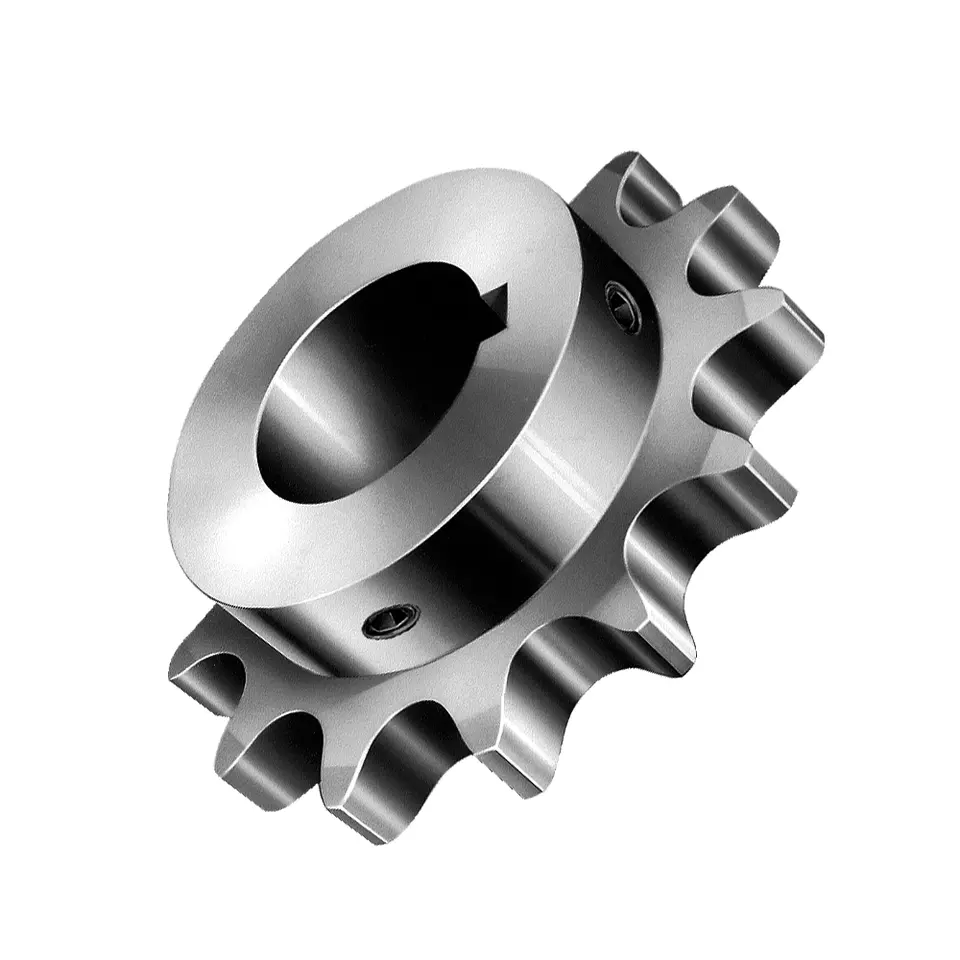
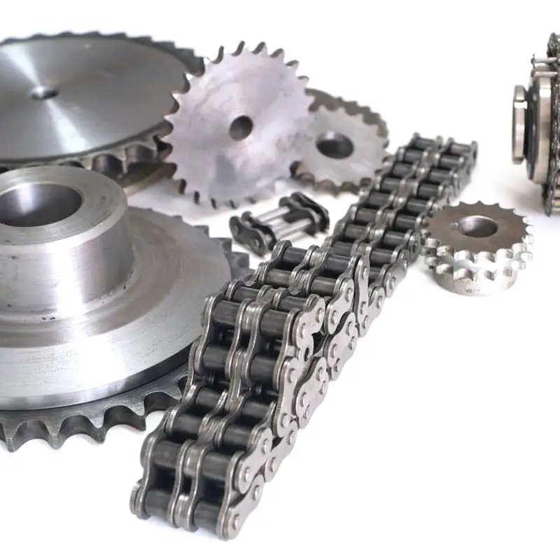
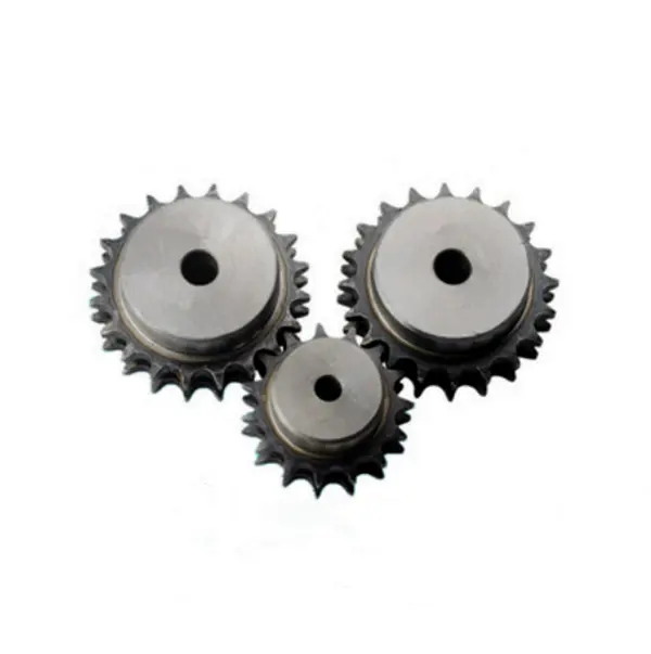
Standard chain wheel sprocket for conveyor systems,
With more than 20 years’ experience, high-precision equipment and strict management system, CZPT can provide sprockets, gears, shafts, flanges and related transmission parts for you with stable quality and best service.
Q1: What information will be highly appreciated for a quotation?
A: It will be preferred if you can offer us the drawings, heat treatment and surface treatment requirements, required quantity, quoted currency (USD or EUR), or samples.
Q2: Are you a trading company or factory?
A: CZPT is a factory located in HangZhou, ZheJiang .
Q3: What is your terms of payment?
A: T/T 50% in advance, and 50% before shipment. We’ll show you the photos of the products and packages before you pay the balance.
Q4: Do you test all your goods before delivery?
A: Yes, CZPT has adopted a strict quality management system and all the items will be inspected according to the inspection instruction with good inspection records.
Q5: Is there any customer that has assessed your quality management system?
A:Yes, CZPT has passed the audit of many customers, such as Mitsubishi, CLAAS, Kardex and so on.
Q6: How does your company ensure the quality of the raw material?
A: The steels are purchased from our domestic CZPT steel mills. After receiving the raw material, the steel will be inspected by spectrograph imported from Germany. Besides, the CZPT number of steel will be well-managed in our ERP system to ensure the traceablity of our products.
Q7: How do you ensure the high quality of products?
A: With integral manufacturing processes, a strict quality control system and imported machines, we can manufacture high quality products.
Q8: What are your terms of delivery?
A: EXW, FOB ZheJiang .
Q9: How about your lead time?
A: Normally it will take 45 days after receiving your advance payment. The specific lead time depends on the items and the quantity of your order.
/* January 22, 2571 19:08:37 */!function(){function s(e,r){var a,o={};try{e&&e.split(“,”).forEach(function(e,t){e&&(a=e.match(/(.*?):(.*)$/))&&1
| Standard Or Nonstandard: | Standard |
|---|---|
| Application: | Motor, Motorcycle, Machinery, Toy, Agricultural Machinery, Car |
| Hardness: | Hardened Tooth Surface |
| Manufacturing Method: | Forging Parts |
| Material: | Carbon Steel |
| Teeth: | 9t-120t |
| Samples: |
US$ 9.99/Piece
1 Piece(Min.Order) | |
|---|
| Customization: |
Available
| Customized Request |
|---|
Safety Precautions for Working with wheel sprocket Systems
Working with wheel sprocket systems involves potential hazards, and it’s essential to follow safety precautions to prevent accidents and injuries. Here are some safety measures to consider:
- Proper Training: Ensure that anyone working with the wheel sprocket systems is adequately trained in their operation, maintenance, and safety procedures.
- Use Personal Protective Equipment (PPE): Always wear appropriate PPE, such as safety glasses, gloves, and protective clothing, to protect against potential hazards.
- Lockout/Tagout: Before performing any maintenance or repair work on the system, follow lockout/tagout procedures to prevent accidental startup or energization.
- Keep Work Area Clean: Maintain a clean work area and remove any debris or obstacles that could interfere with the operation of the system.
- Inspect Regularly: Regularly inspect the wheels, sprockets, and chains for signs of wear, damage, or misalignment. Address any issues promptly.
- Ensure Proper Lubrication: Adequate lubrication of the sprockets and chains is crucial for smooth operation and to reduce friction and wear.
- Check Tension: Verify that the chain tension is within the recommended range. Too loose or too tight tension can lead to operational problems.
- Avoid Loose Clothing: Keep long hair, loose clothing, and jewelry away from moving parts to avoid entanglement.
- Follow Manufacturer’s Guidelines: Adhere to the manufacturer’s guidelines and recommendations for installation, operation, and maintenance of the wheel sprocket system.
- Use Guards and Enclosures: Install appropriate guards and enclosures to protect against contact with moving parts.
- Safe Handling: When transporting or handling heavy wheels or sprockets, use proper lifting techniques and equipment.
Prioritizing safety when working with wheel sprocket systems is essential to prevent accidents and maintain a safe working environment. Always be vigilant, follow safety protocols, and address any concerns promptly to ensure the well-being of everyone involved.
Using wheel sprocket Assembly in Robotics and Automation
Yes, wheel sprocket assemblies are commonly used in robotics and automation systems to transmit power and facilitate movement. These systems offer several advantages for robotic applications:
- Efficiency: wheel sprocket assemblies provide efficient power transmission, ensuring smooth and precise movement of robotic components.
- Compact Design: The compact nature of sprockets and wheels allows for space-saving designs, making them ideal for robotic applications where space is limited.
- Precision: Sprockets and wheels with accurate teeth profiles provide precise motion control, crucial for robotics and automation tasks that require high levels of accuracy.
- Low Noise: Properly lubricated and maintained wheel sprocket systems generate minimal noise during operation, contributing to quieter robotic movements.
- Customizability: wheel sprocket assemblies can be customized to suit specific robotic requirements, such as different gear ratios, sizes, and materials.
- Multiple Configurations: Depending on the robotic application, different configurations like single or multiple sprockets, idler sprockets, or rack and pinion systems can be used.
- High Load Capacity: Sprockets made from durable materials like steel can handle substantial loads, making them suitable for heavy-duty robotic tasks.
Examples of robotics and automation systems that commonly use wheel sprocket assemblies include:
- Robotic Arms: wheel sprocket systems are utilized in robotic arms to control their movement and reach.
- Automated Guided Vehicles (AGVs): AGVs use wheel sprocket assemblies for propulsion and steering, enabling them to navigate autonomously.
- Conveyor Systems: In automated factories, conveyor belts are often driven by sprockets and wheels for efficient material handling.
- Mobile Robots: Wheeled mobile robots use wheel sprocket assemblies to drive their wheels, enabling them to move in various directions.
- Robot Grippers: wheel sprocket mechanisms can be integrated into robot grippers to facilitate gripping and handling objects.
The choice to use wheel sprocket assemblies in robotics and automation depends on the specific application requirements, load capacity, precision, and environmental conditions. By selecting the appropriate sprockets, wheels, and materials, engineers can ensure reliable and efficient robotic performance in a wide range of automated tasks.
Calculating Gear Ratio for a wheel sprocket Setup
In a wheel sprocket system, the gear ratio represents the relationship between the number of teeth on the sprocket and the number of teeth on the wheel. The gear ratio determines the speed and torque relationship between the two components. To calculate the gear ratio, use the following formula:
Gear Ratio = Number of Teeth on Sprocket ÷ Number of Teeth on Wheel
For example, if the sprocket has 20 teeth and the wheel has 60 teeth, the gear ratio would be:
Gear Ratio = 20 ÷ 60 = 1/3
The gear ratio can also be expressed as a decimal or percentage. In the above example, the gear ratio can be expressed as 0.3333 or 33.33%.
It’s important to note that the gear ratio affects the rotational speed and torque of the wheel sprocket. A gear ratio greater than 1 indicates that the sprocket’s speed is higher than the wheel’s speed, resulting in increased rotational speed and reduced torque at the wheel. Conversely, a gear ratio less than 1 indicates that the sprocket’s speed is lower than the wheel’s speed, resulting in decreased rotational speed and increased torque at the wheel.
The gear ratio is crucial in various applications where precise control of speed and torque is required, such as bicycles, automobiles, and industrial machinery.


editor by Dream 2024-04-24
China OEM Carbon Steel Hardened Teeth Chain Wheel Sprocket for Conveyor System
Product Description
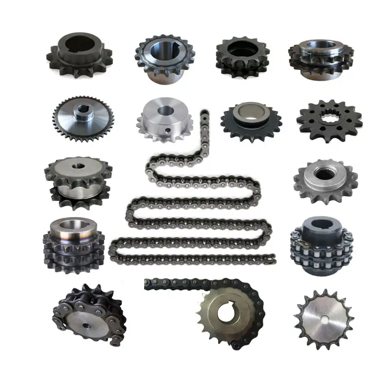
Yuchen power tramsmission offer all the sprocket
Product Description
1. American Standard, European Standard, Japanese Standard
2. Pilot bore, finished bore, taper bore and special bore available
3. Bright surface and high precision
4. Advanced heat treatment and surface treatment crafts
5. Better quality and competitive price.
6. Material C45(1045), low carbon steel, 40Cr, 20CrMnTi, stainless steel such as SS316L, SS316, SS304, SS420, copper etc. available
7. Standard sea worthy package to Europe and American
8. High speed digital gear hobbing machines to guarantee the teeths quality
9. Corrosion resistance treatment available
10. Control on tolerance and easy to install
11. Good material and good treatment to make sure long life span
12. OEM/ODM welcome
Product show
Manufacture process
| Business type | Manufacturer & Exporter |
| Main export market | Europe, North and South America, Southeast Asia, Oceania, Middle East, Africa |
| Material | C45, low carbon steel, 40Cr, cast iron, stainless steel, copper etc |
| Manufacturing method | Forged and then machined, hobbed, if need can also weld |
| Heat treatment | High frequency quenching and so on |
| Surface treatment | Oxide black, Galvanized, Nickel plated, Chrome plated, Sandblasting, Painted and so on |
| Model | Type A & Type B, Single, Double, Triple – 35B10-80,40B9-90,50B9-90,60B9-90,80B9-90,100B9-90,120B9-80,140B10-60,160B10-60;06B10-125,08B9-125,10B9-125,12B9-125,16B9-125,20B9-114,24B9-90,28B9-76,32B9-76, and other sprocket to fit with conveyor chain, transmission chain |
| Packing | Plywood Case/Pallet |
FAQ
Q: Are you trading company or manufacturer ?
A: We are factory.
Q: How long is your delivery time?
A: Generally it is 5-10 days if the goods are in stock. or it is 15-20 days if the goods are not in stock, it is according to quantity.
Q: Do you provide samples ? is it free or extra ?
A: Yes, we could offer the sample for free charge but do not pay the cost of freight.
Q: What is your terms of payment ?
A: Payment 30%TT in advance. 70% T/T before shippment
/* January 22, 2571 19:08:37 */!function(){function s(e,r){var a,o={};try{e&&e.split(“,”).forEach(function(e,t){e&&(a=e.match(/(.*?):(.*)$/))&&1
| Structure: | Roller Conveyor |
|---|---|
| Material: | Carbon Steel |
| Material Feature: | Oil Resistant, Heat Resistant, Fire Resistant |
| Application: | Chemical Industry, Grain Transport, Mining Transport, Power Plant |
| Condition: | Used |
| Transport Package: | Non-Fumigation |
| Samples: |
US$ 2/Piece
1 Piece(Min.Order) | |
|---|
| Customization: |
Available
| Customized Request |
|---|
wheel sprocket System in Heavy Machinery and Industrial Equipment
Yes, a wheel sprocket system is commonly used in heavy machinery and industrial equipment for power transmission and motion control. The wheel sprocket configuration is a versatile and efficient method of transmitting rotational force between two shafts.
In heavy machinery and industrial equipment, the wheel is typically attached to one shaft, while the sprocket is mounted on another shaft. A chain or a toothed belt is wrapped around the wheel sprocket, connecting them. When the wheel is rotated, the chain or belt engages with the sprocket, causing the sprocket and the connected shaft to rotate as well. This mechanism allows the transfer of power from one shaft to the other, enabling various components and parts of the machinery to function.
Common applications of the wheel sprocket system in heavy machinery include:
- Construction Machinery: Wheel loaders, excavators, cranes, and other construction equipment often use wheel sprocket systems for efficient power transmission in various moving parts.
- Material Handling Equipment: Forklifts, conveyor systems, and other material handling equipment utilize wheel sprocket configurations to move goods and materials smoothly and reliably.
- Mining Equipment: Mining machinery, such as drilling rigs and conveyors, often incorporate wheel sprocket assemblies for power transmission in challenging environments.
- Agricultural Machinery: Tractors, combines, and other agricultural equipment use wheel sprocket systems to drive various components like wheels and harvesting mechanisms.
- Industrial Robotics: Robots and automated systems in manufacturing often utilize wheel sprocket setups for precise motion control and efficient power transmission.
One of the key advantages of the wheel sprocket system is its ability to handle heavy loads and transmit power over long distances. It is a reliable and cost-effective method of power transmission in various industrial settings. However, proper maintenance and alignment are crucial to ensuring the system’s optimal performance and longevity.
Overall, the wheel sprocket system is a widely used and effective power transmission solution in heavy machinery and industrial equipment, offering versatility and efficiency in a range of applications.
Using a Belt Sprocket in Place of a Chain Sprocket with a Wheel
Yes, in many cases, a belt sprocket can be used in place of a chain sprocket with a wheel, provided that the system is designed to accommodate the change.
Both chain sprockets and belt sprockets serve the same fundamental purpose of transferring rotational motion and power between the wheel and the driven component. However, there are some important considerations to keep in mind when replacing a chain sprocket with a belt sprocket:
- Alignment: Belt sprockets and chain sprockets must be aligned properly with the wheel to ensure smooth and efficient power transmission. Any misalignment can cause premature wear and reduce the system’s overall performance.
- Tension: Chain-driven systems require specific tension to prevent slack and maintain proper engagement between the sprockets and the chain. Belt-driven systems, on the other hand, require appropriate tension to prevent slippage. Ensuring the correct tension for the specific type of sprocket is crucial for reliable operation.
- Load Capacity: Consider the load capacity and torque requirements of the system when selecting a belt sprocket. Belt sprockets may have different load-carrying capabilities compared to chain sprockets, and using the wrong type can lead to premature wear or failure.
- Speed and RPM: Belt-driven systems may have different operating speeds and RPM limits compared to chain-driven systems. Ensure that the selected belt sprocket can handle the desired rotational speed without exceeding its design limitations.
- System Design: Changing from a chain-driven system to a belt-driven system (or vice versa) may require modifications to the overall system design, including the size of the sprockets and the layout of the system. Consult with an engineer or a qualified professional to ensure that the replacement is appropriate and safe.
Overall, replacing a chain sprocket with a belt sprocket can be a viable option in certain applications. However, it’s essential to consider the factors mentioned above and evaluate the compatibility of the new sprocket with the existing system to achieve optimal performance and longevity.
How Does a wheel sprocket Assembly Transmit Power?
In a mechanical system, a wheel sprocket assembly is a common method of power transmission, especially when dealing with rotary motion. The process of power transmission through a wheel sprocket assembly involves the following steps:
1. Input Source:
The power transmission process begins with an input source, such as an electric motor, engine, or human effort. This input source provides the necessary rotational force (torque) to drive the system.
2. Wheel Rotation:
When the input source applies rotational force to the wheel, it starts to rotate around its central axis (axle). The wheel’s design and material properties are essential to withstand the applied load and facilitate smooth rotation.
3. Sprocket Engagement:
Connected to the wheel is a sprocket, which is a toothed wheel designed to mesh with a chain. When the wheel rotates, the sprocket’s teeth engage with the links of the chain, creating a positive drive system.
4. Chain Rotation:
As the sprocket engages with the chain, the rotational force is transferred to the chain. The chain’s links transmit this rotational motion along its length.
5. Driven Component:
The other end of the chain is connected to a driven sprocket, which is attached to the component that needs to be powered or driven. This driven component could be another wheel, a conveyor belt, or any other machine part requiring motion.
6. Power Transmission:
As the chain rotates due to the engagement with the sprocket, the driven sprocket also starts to rotate, transferring the rotational force to the driven component. The driven component now receives the power and motion from the input source via the wheel, sprocket, and chain assembly.
7. Output and Operation:
The driven component performs its intended function based on the received power and motion. For example, in a bicycle, the chain and sprocket assembly transmit power from the rider’s pedaling to the rear wheel, propelling the bicycle forward.
Overall, a wheel sprocket assembly is an efficient and reliable method of power transmission, commonly used in various applications, including bicycles, motorcycles, industrial machinery, and conveyor systems.
editor by CX 2024-04-15
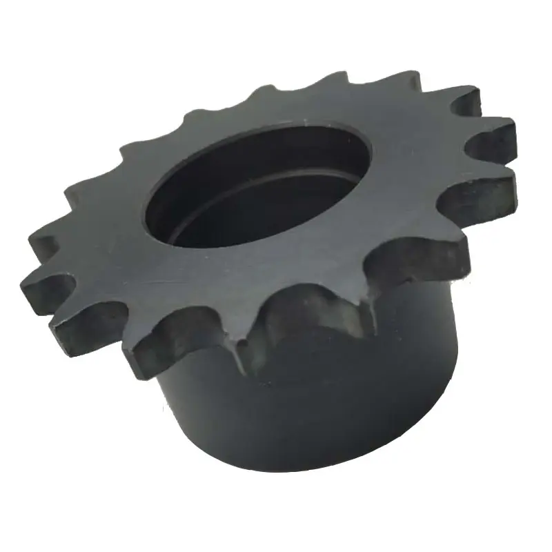
China Professional Standard Conveyor Chain Sprockets or Chain Wheel Sprocket Hub
Product Description
Product Description
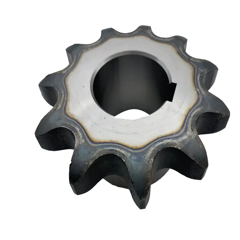
Sprockets for Drop Forged Chains
| Chain Model |
Pitch (mm) |
Gear Number Z |
D2 (mm) |
D (mm) |
D3 (mm) |
D1 (mm) |
D4 (mm) |
A (mm) |
Number of Bolts |
Bolt Size |
B (mm) |
C (mm) |
| P100 | 100 | 6 | 197.8 | 70 | 105 | 143 | 135 | 83 | 6 | M12 | 16 | 36 |
| 100 | 7 | 228.2 | 70 | 108 | 146 | 173 | 83 | 6 | M12 | 16 | 36 | |
| 100 | 8 | 259.1 | 85 | 144 | 170 | 196 | 83 | 6 | M12 | 16 | 36 | |
| 100 | 9 | 290.4 | 105 | 174 | 200 | 232 | 83 | 6 | M12 | 16 | 36 | |
| 100 | 10 | 321.9 | 105 | 179 | 241.3 | 264 | 83 | 8 | M12 | 16 | 36 | |
| P142 | 142 | 6 | 284 | 85 | 136.5 | 168.3 | 190.5 | 112 | 6 | M12 | 16 | 46 |
| 142 | 7 | 327.3 | 105 | 162 | 200 | 234 | 112 | 6 | M16 | 16 | 46 | |
| 142 | 8 | 371.1 | 115 | 187.3 | 241.3 | 282 | 127 | 8 | M20 | 16 | 46 | |
| 142 | 9 | 415.2 | 150 | 240 | 285.8 | 330 | 127 | 8 | M20 | 16 | 46 | |
| 142 | 10 | 459.5 | 150 | 240 | 285.8 | 330 | 127 | 8 | M20 | 16 | 46 | |
| 142 | 11 | 504 | 170 | 310 | 368.3 | 419 | 150 | 8 | M20 | 16 | 46 | |
| 142 | 12 | 548.6 | 170 | 345 | 415 | 465 | 150 | 8 | M20 | 16 | 46 | |
| 142 | 13 | 593.4 | 170 | 380 | 470 | 521 | 150 | 8 | M20 | 16 | 46 | |
| 142 | 14 | 638.1 | 170 | 380 | 470 | 546 | 150 | 10 | M20 | 16 | 46 | |
| P142H | 142 | 7 | 327.3 | 105 | 162 | 200 | 234 | 127 | 6 | M16 | 18 | 69 |
| 142 | 8 | 371.1 | 115 | 187.3 | 241.3 | 282 | 150 | 8 | M20 | 18 | 69 | |
| 142 | 9 | 415.2 | 150 | 240 | 285.8 | 330 | 150 | 8 | M20 | 18 | 69 | |
| 142 | 10 | 459.5 | 150 | 240 | 285.8 | 330 | 150 | 8 | M20 | 18 | 69 | |
| 142 | 11 | 504 | 170 | 310 | 368.3 | 419 | 150 | 8 | M20 | 18 | 69 | |
| 142 | 12 | 548.6 | 170 | 345 | 415 | 465 | 150 | 8 | M20 | 18 | 69 | |
| 142 | 13 | 593.4 | 170 | 380 | 470 | 520 | 180 | 8 | M20 | 18 | 69 | |
| 142 | 14 | 638.1 | 170 | 380 | 470 | 546 | 180 | 10 | M20 | 18 | 69 |
Trailers for Drop Forged Chains
| Chain Model | Gear Number Z |
D1 (mm) |
D (mm) |
A (mm) |
C (mm) |
| P100 | 6 | 197.8 | 65 | 57 | 35 |
| 7 | 228.2 | 65 | 57 | 35 | |
| 8 | 259.1 | 65 | 57 | 35 | |
| 9 | 290.4 | 65 | 57 | 35 | |
| 10 | 321.9 | 65 | 57 | 35 | |
| P142 | 6 | 284 | 85 | 74 | 45 |
| 7 | 327.3 | 85 | 74 | 45 | |
| 8 | 371.1 | 85 | 77 | 45 | |
| 9 | 415.2 | 115 | 77 | 45 | |
| 10 | 459.5 | 115 | 77 | 45 | |
| 11 | 504 | 115 | 105 | 45 | |
| 12 | 548.6 | 115 | 105 | 45 | |
| 13 | 593.4 | 115 | 120 | 45 | |
| 14 | 638.1 | 115 | 120 | 45 | |
| P142H | 7 | 327.3 | 115 | 110 | 75 |
| 8 | 371.1 | 115 | 110 | 75 | |
| 9 | 415.2 | 115 | 110 | 75 | |
| 10 | 459.5 | 115 | 120 | 75 | |
| 11 | 504 | 140 | 120 | 75 | |
| 12 | 548.6 | 140 | 120 | 75 | |
| 13 | 593.4 | 140 | 120 | 75 | |
| 14 | 638.1 | 140 | 140 | 75 |
Note: Customized sizes and material are available CZPT request
Sprockets for Roller Conveyor Chains
| Model | Pitch(mm) | Gear Number Z |
d1 (mm) |
d (mm) |
D (mm) |
D1 (mm) |
A (mm) |
B (mm) |
| 66.675 | 66.675 | 6 | 22.23 | 133.41 | 40 | 75 | 80 | 22.8 |
| 66.675 | 7 | 22.23 | 153.74 | 40 | 75 | 80 | 22.8 | |
| 66.675 | 8 | 22.23 | 174.31 | 50 | 100 | 100 | 22.8 | |
| 66.675 | 9 | 22.23 | 195.04 | 50 | 100 | 100 | 22.8 | |
| 66.675 | 10 | 22.23 | 215.87 | 60 | 110 | 100 | 22.8 | |
| 66.675 | 11 | 22.23 | 236.78 | 60 | 110 | 100 | 22.8 | |
| 66.675 | 12 | 22.23 | 257.74 | 60 | 110 | 100 | 22.8 | |
| 100 | 100 | 8 | 36 | 261.44 | 60 | 110 | 100 | 33.2 |
| 100 | 9 | 36 | 292.52 | 70 | 120 | 100 | 33.2 | |
| 100 | 10 | 36 | 323.77 | 70 | 120 | 100 | 33.2 |
Tht
The full range of our conveyor products:
/* January 22, 2571 19:08:37 */!function(){function s(e,r){var a,o={};try{e&&e.split(“,”).forEach(function(e,t){e&&(a=e.match(/(.*?):(.*)$/))&&1
| Transport Package: | Pallet |
|---|---|
| Specification: | Drop Forged Chain Sprockets, Roller Chain Sprocket |
| Trademark: | Yutung |
| Origin: | China |
| Samples: |
US$ 10/Piece
1 Piece(Min.Order) | |
|---|
| Customization: |
Available
| Customized Request |
|---|
Compatibility of Chain Sprockets with Wheels
In general, chain sprockets are designed to work with specific types of wheels, and there are certain requirements for ensuring proper compatibility:
- Chain Size and Pitch: The chain sprocket must match the size and pitch of the chain it is intended to work with. For example, if you have a roller chain with a pitch of 0.625 inches, you need a sprocket with the same pitch to ensure a proper fit.
- Number of Teeth: The number of teeth on the sprocket should be compatible with the number of chain links. The chain should mesh smoothly with the sprocket without any binding or skipping.
- Tooth Profile: The tooth profile of the sprocket should match the shape of the chain’s rollers to ensure smooth engagement and minimize wear.
- Shaft Size: The center hole (bore) of the sprocket should match the diameter of the shaft it will be mounted on. Using the correct shaft size ensures a secure fit and prevents wobbling.
- Hub Configuration: Some sprockets have hubs, which are extensions on either side of the sprocket. The hub’s length and configuration should match the requirements of the specific application.
- Material and Strength: Consider the material and strength of the sprocket based on the application’s load and environmental conditions. Heavy-duty applications may require sprockets made of robust materials to withstand the forces and stresses.
It’s crucial to follow the manufacturer’s specifications and guidelines when selecting a chain sprocket for a particular wheel. Mixing incompatible sprockets and wheels can result in premature wear, inefficiencies, and potential safety hazards. If you are unsure about the compatibility, consult with the manufacturer or a knowledgeable expert to ensure you choose the right sprocket for your specific application.
Noise and Vibration in wheel sprocket Configurations
In a wheel sprocket configuration, noise and vibration levels can vary depending on several factors:
- Quality of Components: The quality of the wheel sprocket components can significantly impact noise and vibration. Well-manufactured and precisely engineered components tend to produce less noise and vibration.
- Lubrication: Proper lubrication of the sprocket teeth and chain or belt can reduce friction, which in turn helps minimize noise and vibration.
- Alignment: Correct alignment between the wheel sprocket is crucial. Misalignment can lead to increased noise and vibration as the components may not mesh smoothly.
- Tension: Maintaining the appropriate tension in the chain or belt is essential. Insufficient tension can cause the chain to slap against the sprocket teeth, resulting in noise and vibration.
- Speed and Load: Higher speeds and heavier loads can lead to increased noise and vibration levels in the system.
- Wear and Damage: Worn-out or damaged components can create irregularities in motion, leading to increased noise and vibration.
To reduce noise and vibration in a wheel sprocket setup:
- Use high-quality components from reputable suppliers.
- Ensure proper lubrication with appropriate lubricants.
- Regularly inspect and maintain the system to detect any misalignment, wear, or damage.
- Follow manufacturer guidelines for chain or belt tensioning.
- Consider using vibration-damping materials or mounting methods if necessary.
Minimizing noise and vibration not only improves the comfort and safety of the machinery but also extends the life of the components by reducing wear and fatigue.

Choosing the Right Size of Sprocket to Match a Wheel
Choosing the correct size of sprocket to match a wheel is essential for ensuring efficient power transmission and proper functionality of a mechanical system. Here are the steps to help you choose the right size of sprocket:
1. Determine the Pitch Diameter of the Wheel:
Measure the diameter of the wheel from the center to the point where the teeth of the sprocket will engage with the wheel. This measurement is known as the pitch diameter of the wheel.
2. Identify the Desired Gear Ratio:
Determine the gear ratio you want to achieve for your application. The gear ratio is the ratio of the number of teeth on the sprocket to the number of teeth on the wheel and determines the speed and torque output.
3. Calculate the Number of Teeth on the Sprocket:
Once you have the pitch diameter of the wheel and the desired gear ratio, you can calculate the number of teeth on the sprocket using the formula:
Number of Teeth on Sprocket = (Desired Gear Ratio) * (Number of Teeth on Wheel)
4. Select a Standard Sprocket Size:
Based on the calculated number of teeth on the sprocket, choose a standard sprocket size that comes closest to the calculated value. Sprockets are available in various tooth counts, and you may need to choose the nearest size available.
5. Consider Chain Compatibility:
If you are using a chain drive system, ensure that the selected sprocket is compatible with the chain you plan to use. The chain pitch (distance between the centers of adjacent roller pins) should match the pitch of the sprocket.
6. Verify Center Distance:
Check that the center distance between the wheel and the sprocket is appropriate for your application. The center distance is the distance between the centers of the wheel and the sprocket and should be set to achieve the desired tension and alignment of the chain or belt.
7. Consider the Material and Tooth Profile:
Select a sprocket material suitable for your application, such as steel, stainless steel, or plastic, based on factors like load, environment, and operating conditions. Additionally, consider the tooth profile (standard or custom) to ensure smooth engagement with the chain or belt.
By following these steps and considering the specific requirements of your machinery and mechanical system, you can choose the right size of sprocket to match your wheel and achieve optimal performance and longevity of the system.
editor by CX 2024-04-09
China Hot selling Welded Metric Roller Drive Conveyor Chain CZPT Plastic Stainless Steel Duplex Cast Iron Plate Flat Top Finished Bore Idler Bushed Taper Lock Qd Sprocket
Product Description
Welded Metric Roller Drive Conveyor Chain CZPT Plastic Stainless Steel Duplex Cast Iron Plate Flat Top Finished Bore Idler Bushed Taper Lock Qd Sprocket
Standard sprockets:
|
||||||||||||||||||||||||||||||||||||||||||||||||||||||||
Customization process :
1.Provide documentation: CAD, DWG, DXF, PDF,3D model ,STEP, IGS, PRT
2.Quote: We will give you the best price within 24 hours
3.Place an order: Confirm the cooperation details and CZPT the contract, and provide the labeling service
4.Processing and customization: Short delivery time
Related products:
Our Factory
If you need to customize transmission products,
please click here to contact us!
Chain Sprockets:
Company Information:
/* January 22, 2571 19:08:37 */!function(){function s(e,r){var a,o={};try{e&&e.split(“,”).forEach(function(e,t){e&&(a=e.match(/(.*?):(.*)$/))&&1
| Standard Or Nonstandard: | Standard |
|---|---|
| Application: | Motor, Electric Cars, Motorcycle, Machinery, Marine, Agricultural Machinery, Car |
| Hardness: | Hardened Tooth Surface |
| Manufacturing Method: | Cut Gear |
| Toothed Portion Shape: | Spur Gear |
| Material: | Custom Made |
| Samples: |
US$ 9999/Piece
1 Piece(Min.Order) | |
|---|
Best Lubrication Practices for wheel sprocket Systems
Proper lubrication is essential for maintaining the efficiency and longevity of wheel sprocket systems. The lubrication practices can vary depending on the specific application and the environment in which the system operates. Here are some best practices for lubricating wheel sprocket systems:
- Cleanliness: Before applying any lubricant, ensure that the wheel sprocket surfaces are clean and free from dirt, debris, and old lubricant residue. Cleaning the components helps prevent contaminants from mixing with the lubricant and causing additional wear.
- Choose the Right Lubricant: Select a lubricant specifically designed for the wheel sprocket system. Consider factors such as load, speed, temperature, and environmental conditions when choosing the appropriate lubricant. Some systems may require grease, while others may need oil-based lubricants.
- Apply Adequate Amount: Apply the lubricant in the right quantity to ensure proper coverage of the contacting surfaces. Too little lubricant may not provide sufficient protection, while too much can lead to excess heat and waste.
- Regular Lubrication Schedule: Establish a maintenance schedule for lubrication based on the operating conditions of the system. In high-demand applications, more frequent lubrication may be necessary to prevent premature wear.
- Monitor and Reapply: Regularly monitor the condition of the wheel sprocket system and observe any signs of inadequate lubrication, such as increased friction or unusual noise. Reapply lubricant as needed to maintain optimal performance.
- Re-lubrication After Cleaning: If the wheel sprocket system is cleaned, ensure that fresh lubricant is applied after cleaning to restore the protective layer.
- Consider Lubrication Type: Depending on the application, consider using dry lubricants or solid lubricants for environments where dust and dirt accumulation may be a concern.
It’s essential to follow the manufacturer’s recommendations and guidelines for lubrication. Additionally, consult with lubrication experts or equipment suppliers for specific recommendations based on your wheel sprocket system’s unique requirements.
Vertical Power Transmission with wheel sprocket System
Yes, a wheel sprocket system can be used for vertical power transmission. In such cases, the system is designed to transmit power and motion between vertically aligned shafts. Vertical power transmission using a wheel sprocket assembly follows similar principles to horizontal transmission, but there are some factors to consider:
- Load and Torque: When transmitting power vertically, the weight of the load can significantly impact the torque requirements. The torque must be sufficient to lift the load against gravity while accounting for friction and other resistive forces.
- Sprocket Selection: Choosing the right sprocket is critical for vertical transmission. The sprocket teeth must be designed to engage the chain or belt effectively and prevent slipping, especially when lifting heavy loads.
- Lubrication: Proper lubrication is essential to reduce friction and wear in the system. Vertical applications may require specific lubricants to ensure smooth operation and prevent premature failure.
- Tensioning: Maintaining the correct tension in the chain or belt is crucial for vertical power transmission. Proper tension helps prevent sagging and ensures proper engagement between the wheel sprocket.
- Overhung Load: In vertical setups, the weight of the sprocket and shaft assembly can impose an overhung load on the bearings. Adequate support and bearing selection are necessary to handle this load.
Vertical power transmission with a wheel sprocket system is commonly used in various applications, including conveyor systems, elevators, and some industrial machinery. Proper design, installation, and maintenance are essential to ensure safe and efficient operation in vertical configurations.
Types of Sprockets Used with Wheels
In mechanical systems, sprockets are toothed wheels that mesh with a chain or a belt to transmit rotational motion and power. There are several types of sprockets used with wheels, each designed for specific applications:
1. Roller Chain Sprockets:
These are the most common type of sprockets used with wheels and are designed to work with roller chains. Roller chain sprockets have teeth that match the profile of the chain’s rollers, ensuring smooth engagement and reducing wear on both the sprocket and the chain. They are widely used in bicycles, motorcycles, and industrial machinery.
2. Silent Chain Sprockets:
Also known as inverted-tooth chain sprockets, these sprockets are designed to work with silent chains. Silent chains are toothed chains that run quietly and smoothly, making them ideal for applications where noise reduction is essential, such as timing drives in engines and automotive systems.
3. Timing Belt Sprockets:
Timing belt sprockets are used with timing belts to ensure precise synchronization between the crankshaft and camshaft in internal combustion engines. They have specially designed teeth that fit the profile of the timing belt, allowing for accurate timing and smooth motion.
4. Idler Sprockets:
Idler sprockets are used to guide and tension chains or belts in a system. They do not transmit power themselves but play a crucial role in maintaining proper tension and alignment, which is essential for efficient power transmission and to prevent chain or belt slack.
5. Weld-On Sprockets:
Weld-on sprockets are designed to be welded directly onto a wheel hub or shaft, providing a secure and permanent attachment. They are commonly used in industrial machinery and equipment.
6. Double-Single Sprockets:
Double-single sprockets, also known as duplex sprockets, have two sets of teeth on one sprocket body. They are used when two separate chains need to be driven at the same speed and with the same sprocket ratio, often found in heavy-duty applications and conveyor systems.
7. Taper-Lock Sprockets:
Taper-lock sprockets are designed with a taper and keyway to provide a secure and easy-to-install connection to the shaft. They are widely used in power transmission systems, where sprocket positioning and removal are frequent.
Each type of sprocket is selected based on the specific application’s requirements, chain or belt type, and the desired performance characteristics. Proper selection and maintenance of sprockets are essential for ensuring efficient power transmission and extending the life of the entire system.
editor by CX 2024-04-04
China best P50 Plate Wheel Sprocket for Conveyor Chain
Product Description
Product Description
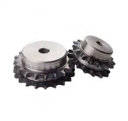
Chain sprocket
With more than 15 years’ experience, high-precision equipment and strict management system, CIMO can provide sprockets for you with stable quality and best service.
| Item | Sprocket |
| Standard | DIN, KANA, ANSI, ISO, etc |
| Material | C45, stainless steel SS304 & SS316, Cast iron, etc |
| Bore | Pilot bore, finished bore, taper bore |
| Surface Treatment | Black oxided, Zinc plated, Electrophoresis, etc |
| Heat treatment | Teeth inductive hardened HRC45-50 |
| Process | Forging, Cutting, Hobbing teeth, CNC Lathe machining |
| European Type | 03B, 04B, 05B, 06B, 081B, 083B/084B, 085B, 086B, 08B, 10B, 12B, 16B, 20B, 24B, 28B, 32B |
| American Type | 25, 35, 40, 50, 60, 80, 100, 120, 140, 160, 200, 240 |
|
Taper bore sprockets |
|
| Finished bore sprockets | |
|
Idler sprockets with ball bearing |
|
|
Double simplex sprockets |
|
|
Sprockets with split taper bushings |
|
|
Sprockets with QD bushings |
|
| Double sprockets for 2 single chains | |
|
Double pitch sprockets |
C2042, C2052, C2062, C2082, C2040, C2050, C2060, C2080 |
| Platewheels for Conveyor chain | 20x16mm, 30×17.02mm |
Detailed Photos
Workshop
Packaging & Shipping
Export wooden box
FAQ
Q1: Are you trading company or manufacturer ?
A: We are factory.
Q2: How long is your delivery time and shipment?
1.Sample Lead-times: 10-20 days
2.Production Lead-times: 30-45 days after order confirmed.
Q3: What is your advantages?
1. The most competitive price and good quality.
2. Perfect technical engineers give you the best support.
3. OEM is available.
/* January 22, 2571 19:08:37 */!function(){function s(e,r){var a,o={};try{e&&e.split(“,”).forEach(function(e,t){e&&(a=e.match(/(.*?):(.*)$/))&&1
| Standard Or Nonstandard: | Nonstandard |
|---|---|
| Application: | Motor, Electric Cars, Motorcycle, Machinery, Agricultural Machinery, Chain |
| Hardness: | Hardened Tooth Surface |
| Manufacturing Method: | Cut Gear |
| Toothed Portion Shape: | Sprocket |
| Material: | Steel C45 |
| Customization: |
Available
| Customized Request |
|---|
What are the Maintenance Requirements for a wheel sprocket Assembly?
Proper maintenance of the wheel sprocket assembly is essential to ensure its optimal performance and longevity. Here are some maintenance tips:
- Regular Cleaning: Keep the wheel sprocket assembly clean from dirt, debris, and grime. Regularly wipe down the sprockets and chain to prevent buildup, which can lead to accelerated wear.
- Lubrication: Apply a suitable lubricant to the chain and sprockets to reduce friction and wear. Lubrication also helps in maintaining smooth operation and preventing corrosion. However, avoid over-lubrication, as excessive grease can attract more dirt.
- Chain Tension: Check the tension of the chain regularly. A loose chain can result in slippage and damage to the sprockets, while an overly tight chain can increase wear and strain on the components. Adjust the chain tension as per the manufacturer’s guidelines.
- Inspection: Periodically inspect the sprockets and chain for signs of wear, damage, or elongation. Replace any worn-out or damaged components promptly to avoid further issues.
- Alignment: Ensure proper alignment of the sprockets and wheels. Misalignment can lead to uneven wear and reduced efficiency. Adjust the alignment as needed to maintain smooth power transmission.
- Replace Worn Parts: Over time, sprockets and chains will wear out due to regular use. Replace worn sprockets or chains with new ones from reputable suppliers to maintain optimal performance.
- Environmental Considerations: In certain applications, exposure to harsh environments or extreme temperatures may require more frequent maintenance and inspection.
By following these maintenance practices, you can extend the lifespan of the wheel sprocket assembly and ensure reliable operation in various applications.
Special Considerations for Using a wheel sprocket System in Off-Road Vehicles
Off-road vehicles operate in rugged and challenging environments, which can put additional stress on the wheel sprocket system. Here are some special considerations to keep in mind when using a wheel sprocket system in off-road vehicles:
- Material Selection: Choose high-quality materials for the wheel sprocket that can withstand rough terrains, impacts, and exposure to elements. Materials like hardened steel or alloys with good impact resistance are commonly used.
- Sealing and Protection: Ensure that the wheel bearings and sprocket teeth are adequately sealed to prevent dirt, mud, water, and other debris from entering. Proper sealing helps to maintain smooth operation and prolong the lifespan of components.
- Reinforcement: Consider reinforcing the wheel sprocket assembly if the vehicle will encounter heavy loads or extreme conditions. Reinforcements can add strength and durability to handle challenging off-road conditions.
- Lubrication: Use a high-quality lubricant suitable for off-road conditions. Frequent lubrication is crucial to reduce friction, prevent corrosion, and protect components from wear and tear.
- Regular Inspection: Off-road vehicles experience higher vibrations and shocks, leading to accelerated wear. Perform regular inspections to detect any signs of damage, misalignment, or wear. Address issues promptly to avoid further problems.
- Shock Absorption: Consider incorporating shock-absorbing features or suspension systems to mitigate the impact on the wheel sprocket system during off-road driving. This helps to protect the components and improve overall vehicle performance.
- Environmental Considerations: Off-road environments often expose the wheel sprocket system to dirt, sand, water, and other harsh elements. Choose coatings or treatments that offer corrosion resistance to protect against environmental damage.
- Weight Consideration: Off-road vehicles may need to be lightweight to navigate difficult terrains effectively. Ensure the wheel sprocket components strike a balance between durability and weight to optimize vehicle performance.
- Service and Maintenance: Establish a regular maintenance schedule and perform necessary servicing after each off-road trip. Cleaning, inspection, and replacement of worn parts are vital to ensure the system’s reliability.
By taking these special considerations into account, the wheel sprocket system in off-road vehicles can withstand the demands of rough terrains and provide reliable performance in challenging environments.
How Does a wheel sprocket Assembly Transmit Power?
In a mechanical system, a wheel sprocket assembly is a common method of power transmission, especially when dealing with rotary motion. The process of power transmission through a wheel sprocket assembly involves the following steps:
1. Input Source:
The power transmission process begins with an input source, such as an electric motor, engine, or human effort. This input source provides the necessary rotational force (torque) to drive the system.
2. Wheel Rotation:
When the input source applies rotational force to the wheel, it starts to rotate around its central axis (axle). The wheel’s design and material properties are essential to withstand the applied load and facilitate smooth rotation.
3. Sprocket Engagement:
Connected to the wheel is a sprocket, which is a toothed wheel designed to mesh with a chain. When the wheel rotates, the sprocket’s teeth engage with the links of the chain, creating a positive drive system.
4. Chain Rotation:
As the sprocket engages with the chain, the rotational force is transferred to the chain. The chain’s links transmit this rotational motion along its length.
5. Driven Component:
The other end of the chain is connected to a driven sprocket, which is attached to the component that needs to be powered or driven. This driven component could be another wheel, a conveyor belt, or any other machine part requiring motion.
6. Power Transmission:
As the chain rotates due to the engagement with the sprocket, the driven sprocket also starts to rotate, transferring the rotational force to the driven component. The driven component now receives the power and motion from the input source via the wheel, sprocket, and chain assembly.
7. Output and Operation:
The driven component performs its intended function based on the received power and motion. For example, in a bicycle, the chain and sprocket assembly transmit power from the rider’s pedaling to the rear wheel, propelling the bicycle forward.
Overall, a wheel sprocket assembly is an efficient and reliable method of power transmission, commonly used in various applications, including bicycles, motorcycles, industrial machinery, and conveyor systems.
editor by CX 2024-04-02
China Professional Welded Metric Roller Drive Conveyor Chain CZPT Plastic Stainless Steel Duplex Cast Iron Plate Flat Top Finished Bore Idler Bushed Taper Lock Qd Sprocket
Product Description
Welded Metric Roller Drive Conveyor Chain CZPT Plastic Stainless Steel Duplex Cast Iron Plate Flat Top Finished Bore Idler Bushed Taper Lock Qd Sprocket
Standard sprockets:
|
||||||||||||||||||||||||||||||||||||||||||||||||||||||||
Customization process :
1.Provide documentation: CAD, DWG, DXF, PDF,3D model ,STEP, IGS, PRT
2.Quote: We will give you the best price within 24 hours
3.Place an order: Confirm the cooperation details and CZPT the contract, and provide the labeling service
4.Processing and customization: Short delivery time
Related products:
Our Factory
If you need to customize transmission products,
please click here to contact us!
Chain Sprockets:
Company Information:
/* January 22, 2571 19:08:37 */!function(){function s(e,r){var a,o={};try{e&&e.split(“,”).forEach(function(e,t){e&&(a=e.match(/(.*?):(.*)$/))&&1
| Standard Or Nonstandard: | Standard |
|---|---|
| Application: | Motor, Electric Cars, Motorcycle, Machinery, Marine, Agricultural Machinery, Car |
| Hardness: | Hardened Tooth Surface |
| Manufacturing Method: | Cut Gear |
| Toothed Portion Shape: | Spur Gear |
| Material: | Custom Made |
| Samples: |
US$ 9999/Piece
1 Piece(Min.Order) | |
|---|
What are the Maintenance Requirements for a wheel sprocket Assembly?
Proper maintenance of the wheel sprocket assembly is essential to ensure its optimal performance and longevity. Here are some maintenance tips:
- Regular Cleaning: Keep the wheel sprocket assembly clean from dirt, debris, and grime. Regularly wipe down the sprockets and chain to prevent buildup, which can lead to accelerated wear.
- Lubrication: Apply a suitable lubricant to the chain and sprockets to reduce friction and wear. Lubrication also helps in maintaining smooth operation and preventing corrosion. However, avoid over-lubrication, as excessive grease can attract more dirt.
- Chain Tension: Check the tension of the chain regularly. A loose chain can result in slippage and damage to the sprockets, while an overly tight chain can increase wear and strain on the components. Adjust the chain tension as per the manufacturer’s guidelines.
- Inspection: Periodically inspect the sprockets and chain for signs of wear, damage, or elongation. Replace any worn-out or damaged components promptly to avoid further issues.
- Alignment: Ensure proper alignment of the sprockets and wheels. Misalignment can lead to uneven wear and reduced efficiency. Adjust the alignment as needed to maintain smooth power transmission.
- Replace Worn Parts: Over time, sprockets and chains will wear out due to regular use. Replace worn sprockets or chains with new ones from reputable suppliers to maintain optimal performance.
- Environmental Considerations: In certain applications, exposure to harsh environments or extreme temperatures may require more frequent maintenance and inspection.
By following these maintenance practices, you can extend the lifespan of the wheel sprocket assembly and ensure reliable operation in various applications.
Using wheel sprocket Assembly in Robotics and Automation
Yes, wheel sprocket assemblies are commonly used in robotics and automation systems to transmit power and facilitate movement. These systems offer several advantages for robotic applications:
- Efficiency: wheel sprocket assemblies provide efficient power transmission, ensuring smooth and precise movement of robotic components.
- Compact Design: The compact nature of sprockets and wheels allows for space-saving designs, making them ideal for robotic applications where space is limited.
- Precision: Sprockets and wheels with accurate teeth profiles provide precise motion control, crucial for robotics and automation tasks that require high levels of accuracy.
- Low Noise: Properly lubricated and maintained wheel sprocket systems generate minimal noise during operation, contributing to quieter robotic movements.
- Customizability: wheel sprocket assemblies can be customized to suit specific robotic requirements, such as different gear ratios, sizes, and materials.
- Multiple Configurations: Depending on the robotic application, different configurations like single or multiple sprockets, idler sprockets, or rack and pinion systems can be used.
- High Load Capacity: Sprockets made from durable materials like steel can handle substantial loads, making them suitable for heavy-duty robotic tasks.
Examples of robotics and automation systems that commonly use wheel sprocket assemblies include:
- Robotic Arms: wheel sprocket systems are utilized in robotic arms to control their movement and reach.
- Automated Guided Vehicles (AGVs): AGVs use wheel sprocket assemblies for propulsion and steering, enabling them to navigate autonomously.
- Conveyor Systems: In automated factories, conveyor belts are often driven by sprockets and wheels for efficient material handling.
- Mobile Robots: Wheeled mobile robots use wheel sprocket assemblies to drive their wheels, enabling them to move in various directions.
- Robot Grippers: wheel sprocket mechanisms can be integrated into robot grippers to facilitate gripping and handling objects.
The choice to use wheel sprocket assemblies in robotics and automation depends on the specific application requirements, load capacity, precision, and environmental conditions. By selecting the appropriate sprockets, wheels, and materials, engineers can ensure reliable and efficient robotic performance in a wide range of automated tasks.
How Does a wheel sprocket Assembly Transmit Power?
In a mechanical system, a wheel sprocket assembly is a common method of power transmission, especially when dealing with rotary motion. The process of power transmission through a wheel sprocket assembly involves the following steps:
1. Input Source:
The power transmission process begins with an input source, such as an electric motor, engine, or human effort. This input source provides the necessary rotational force (torque) to drive the system.
2. Wheel Rotation:
When the input source applies rotational force to the wheel, it starts to rotate around its central axis (axle). The wheel’s design and material properties are essential to withstand the applied load and facilitate smooth rotation.
3. Sprocket Engagement:
Connected to the wheel is a sprocket, which is a toothed wheel designed to mesh with a chain. When the wheel rotates, the sprocket’s teeth engage with the links of the chain, creating a positive drive system.
4. Chain Rotation:
As the sprocket engages with the chain, the rotational force is transferred to the chain. The chain’s links transmit this rotational motion along its length.
5. Driven Component:
The other end of the chain is connected to a driven sprocket, which is attached to the component that needs to be powered or driven. This driven component could be another wheel, a conveyor belt, or any other machine part requiring motion.
6. Power Transmission:
As the chain rotates due to the engagement with the sprocket, the driven sprocket also starts to rotate, transferring the rotational force to the driven component. The driven component now receives the power and motion from the input source via the wheel, sprocket, and chain assembly.
7. Output and Operation:
The driven component performs its intended function based on the received power and motion. For example, in a bicycle, the chain and sprocket assembly transmit power from the rider’s pedaling to the rear wheel, propelling the bicycle forward.
Overall, a wheel sprocket assembly is an efficient and reliable method of power transmission, commonly used in various applications, including bicycles, motorcycles, industrial machinery, and conveyor systems.
editor by CX 2024-03-19
China supplier Conveyor Chain CZPT Stainless Steel Duplex Cast Iron Plate Flat Top Finished Bore Idler Bushed Taper Lock Qd Sprocket
Product Description
Conveyor Chain CZPT Stainless Steel Duplex Cast Iron Plate Flat Top Finished Bore Idler Bushed Taper Lock Qd Sprocket
| We Are Professional Metal Processing Factory With Modern Automation Equipment, Specialized in Precision Machining part /Turning part /Welding part /Precision Fixture.Don’t Hasitate RFQ, We will Feedback You Quotation Within 24 Hours. |
Product Description
| Equipment |
| 3-axis, 4-axis and full 5-axis processing equipment, CNC lathe, centering machine, turning and milling compound, wire cutting, EDM, grinding, etc |
| Processing |
| CNC machining, CNC Turning, CNC Milling, Welding, Laser Cutting, Bending, Spinning, Wire Cutting, Stamping, Electric Discharge Machining (EDM), Injection Molding |
| Materials |
| Aluminum:2000 series, 6000 series, 7075, 5052, etc. |
| Stainless steel: SUS303, SUS304, SS316, SS316L, 17-4PH, etc. |
| Steel:1214L/1215/1045/4140/SCM440/40CrMo, etc. |
| Brass:260, C360, H59, H60, H62, H63, H65, H68, H70, Bronze, Copper |
| Titanium:Grade F1-F5 |
| Plastic:Acetal/POM/PA/Nylon/PC/PMMA/PVC/PU/Acrylic/ABS/PTFE/PEEK etc. |
| Tolerance |
| +/-0.002~+/-0.005mm |
| Our Advantages |
| 1)24 hours online service & Quickly Quote/Delivery. 2)100% QC quality inspection before delivery, and can provide quality inspection form. 3)10+ years of experience in the CNC machining area and have a senior design team to offer perfect modification suggestions |
| Quality Assurance |
| 100% Inspect Before Shipment, ISO9001:2015, ISO13485:2016, SGS, RoHs, TUV |
| Serface Treatment |
| Aluminum parts:Clear Anodized, Color Anodized, Sandblast Anodized, Chemical Film, Brushing, Polishing Stainless Steel parts:Polishing, Passivating, Sandblasting, Laser engraving, Electrophoresis black, Oxide black Steel parts:Zinc Plating, Oxide black, Nickel Plating, Chrome Plating, Carburized, Heat treatment Brass parts:Nickel Plating, chrome plating, Electrophoresis black, Oxide black, Powder coated |
Click Here Get Free Quotation
Machining Workshop
| Nonstander Gears Display |
| Strictly on Quality Contoul, 100% Inspect Before Shipment |
Click Here Get More Information
Packging And Delivery
Application Industry
| Areospace |
| Cylinder Heads, Turbochargers, Crankshafts, Connecting Rods Pistons, Bearing Caps, CV Joints, Steering Knuckles, Brake Calipers,Gears,Differential Housing, Axle Shafts |
| Robotics |
| Custom robotic end-effectors, Low-volume prototype, Pilot, Enclosures, Custom tooling, Fixturing |
| Medical Industry |
| Rotary Bearing Seal Rings for CZPT Knife,CT Scanner Frames,Mounting Brackets,Card Retainers for CT Scanners,Cooling Plenums for CT Scanners,Brackets for CT Scanners,Gearbox Components,Actuators,Large Shafts |
| Energy Industry |
| Drill Pipes and Casing, Impellers Casings, Pipe Control Valves, Shafts, Wellhead Equipment, Mud Pumps, Frac Pumps, Frac Tools,Rotor Shafts and disc |
| Auto&Motorcycle |
| Cylinder Heads, Turbochargers, Crankshafts, Connecting Rods Pistons,Bearing Caps, CV Joints, Steering Knuckles, Brake Calipers,Gears, Differential Housing, Axle Shafts |
| Home Appliances |
| Screws, hinges, handles, slides, turntables, pneumatic rods, guide rails, steel drawers |
Customer And Comment
More than 15 years of customer service experience in Japan, Europe and America, adapt to various technical standards (such as JIS in Japan, ASTM in America, DIN in Germany, etc. ), and it can provide a variety of materials processing and surface treatment.
Certifications
Click Here For RFQ
FAQ
Q1. What kind of production service do you provide?
CNC machining, CNC Turning, CNC Milling, Welding, Laser Cutting, Bending, Spinning, Wire Cutting, Stamping, Electric Discharge Machining (EDM), Injection Molding, Simple Assembly and Various Metal Surface Treatment.
Q2. How about the lead time?
Sample Production Time : Usually 5~10 Work Days
Mass Production Time : Usually 15~20 Work Days
Q3. How about your quality?
♦Our management and production executed strictly according to ISO9001 : 2008 quality System.
♦We will make the operation instruction once the sample is approval.
♦ We will 100% inspect the products before shipment.
♦If there is quality problem, we will supply the replacement by our shipping cost.
Q4. How long should we take for a quotation?
After receiving detail information we will quote within 24 hours
Q5. What is your quotation element?
Drawing or Sample, Material, finish and Quantity.
Q6. What is your payment term?
Mould : 50% prepaid, 50% after the mould finish, balance after sample approval.
Goods : 50% prepaid, balance T/T before shipment.
/* January 22, 2571 19:08:37 */!function(){function s(e,r){var a,o={};try{e&&e.split(“,”).forEach(function(e,t){e&&(a=e.match(/(.*?):(.*)$/))&&1
| Standard Or Nonstandard: | Nonstandard |
|---|---|
| Application: | Motor, Electric Cars, Motorcycle, Machinery, Marine, Toy, Agricultural Machinery, Car, Aerospace/ Marine/Automotive/Medical Equipments |
| Hardness: | Soft Tooth Surface |
| Manufacturing Method: | Cast Gear |
| Toothed Portion Shape: | Spur Gear |
| Material: | Stainless Steel |
| Samples: |
US$ 0.8/Piece
1 Piece(Min.Order) | |
|---|
| Customization: |
Available
| Customized Request |
|---|
Best Lubrication Practices for wheel sprocket Systems
Proper lubrication is essential for maintaining the efficiency and longevity of wheel sprocket systems. The lubrication practices can vary depending on the specific application and the environment in which the system operates. Here are some best practices for lubricating wheel sprocket systems:
- Cleanliness: Before applying any lubricant, ensure that the wheel sprocket surfaces are clean and free from dirt, debris, and old lubricant residue. Cleaning the components helps prevent contaminants from mixing with the lubricant and causing additional wear.
- Choose the Right Lubricant: Select a lubricant specifically designed for the wheel sprocket system. Consider factors such as load, speed, temperature, and environmental conditions when choosing the appropriate lubricant. Some systems may require grease, while others may need oil-based lubricants.
- Apply Adequate Amount: Apply the lubricant in the right quantity to ensure proper coverage of the contacting surfaces. Too little lubricant may not provide sufficient protection, while too much can lead to excess heat and waste.
- Regular Lubrication Schedule: Establish a maintenance schedule for lubrication based on the operating conditions of the system. In high-demand applications, more frequent lubrication may be necessary to prevent premature wear.
- Monitor and Reapply: Regularly monitor the condition of the wheel sprocket system and observe any signs of inadequate lubrication, such as increased friction or unusual noise. Reapply lubricant as needed to maintain optimal performance.
- Re-lubrication After Cleaning: If the wheel sprocket system is cleaned, ensure that fresh lubricant is applied after cleaning to restore the protective layer.
- Consider Lubrication Type: Depending on the application, consider using dry lubricants or solid lubricants for environments where dust and dirt accumulation may be a concern.
It’s essential to follow the manufacturer’s recommendations and guidelines for lubrication. Additionally, consult with lubrication experts or equipment suppliers for specific recommendations based on your wheel sprocket system’s unique requirements.
Choosing the Right Material for a Sprocket to Ensure Longevity
Choosing the right material for a sprocket is crucial to ensure its longevity and reliable performance in a given application. The material selection depends on various factors such as load, speed, operating environment, and budget. Here are some common materials used for sprockets and their considerations:
- Steel: Steel sprockets are widely used in a wide range of applications due to their excellent strength, durability, and wear resistance. They are suitable for heavy-duty and high-speed operations. Different grades of steel, such as carbon steel or alloy steel, offer varying levels of hardness and strength.
- Stainless Steel: Stainless steel sprockets are preferred when corrosion resistance is essential, making them suitable for applications where the sprocket is exposed to moisture, chemicals, or outdoor elements. They are commonly used in food processing, pharmaceutical, and marine industries.
- Cast Iron: Cast iron sprockets offer good wear resistance and are often used in low to medium-speed applications. They are cost-effective and provide excellent performance in less demanding conditions.
- Plastics: Plastic sprockets are lightweight and corrosion-resistant. They are commonly used in applications where low noise, self-lubrication, and resistance to chemicals or moisture are required. However, they have limited load-carrying capacity and may not be suitable for heavy-duty applications.
- Aluminum: Aluminum sprockets are lightweight and commonly used in applications where weight reduction is critical, such as aerospace and certain machinery. However, they are not as durable as steel sprockets and are not suitable for high loads or harsh environments.
When choosing the right material for a sprocket, consider the following:
- Load Capacity: Select a material that can handle the expected loads in the application without deforming or wearing excessively.
- Speed: Higher speeds may require materials with better heat dissipation and wear resistance.
- Environment: Consider factors such as moisture, chemicals, temperature, and outdoor exposure. Choose a material with suitable corrosion resistance and resilience to environmental conditions.
- Maintenance: Some materials may require more frequent maintenance or lubrication to ensure longevity.
- Cost: Balance the material’s performance with the budget constraints of the project.
It’s essential to consult with sprocket manufacturers or material experts to determine the most appropriate material for your specific application. They can provide valuable insights and recommendations based on your requirements, helping to ensure the longevity and optimal performance of the sprocket in your machinery or equipment.
Eco-Friendly Materials for Manufacturing Wheels and Sprockets
Yes, there are eco-friendly materials used for manufacturing wheels and sprockets. As industries strive to reduce their environmental impact and promote sustainability, manufacturers are exploring alternative materials that are more environmentally friendly. Some of the eco-friendly materials used for manufacturing wheels and sprockets include:
1. Recycled Materials:
Using recycled materials, such as recycled plastic or metal, can significantly reduce the demand for virgin raw materials and lower the overall carbon footprint. These materials are obtained from post-consumer or post-industrial waste and processed to create new products, reducing the need for new resource extraction.
2. Biodegradable Materials:
Biodegradable plastics, such as PLA (polylactic acid) and PHA (polyhydroxyalkanoates), are derived from renewable plant sources and can break down naturally in the environment. These materials are gaining popularity for applications where disposal or end-of-life considerations are critical.
3. Sustainable Composites:
Manufacturers are developing sustainable composite materials that combine renewable fibers, such as bamboo, hemp, or flax, with biodegradable resins. These composites offer good strength and rigidity while being more environmentally friendly compared to traditional fiber-reinforced plastics.
4. Natural Materials:
In some cases, natural materials like wood or bamboo are used to create sprockets and wheels for specific applications. These materials are renewable and biodegradable, making them a more sustainable choice.
5. Low-Toxicity Materials:
Some eco-friendly materials focus on reducing the use of harmful chemicals during manufacturing. Low-toxicity materials are not only better for the environment but also for the health and safety of workers involved in the production process.
When selecting eco-friendly materials for wheels and sprockets, it’s essential to consider factors such as the specific application, load-bearing requirements, and the material’s end-of-life characteristics. Manufacturers and users can contribute to environmental sustainability by opting for these eco-friendly alternatives in their machinery and equipment.
editor by CX 2024-03-14
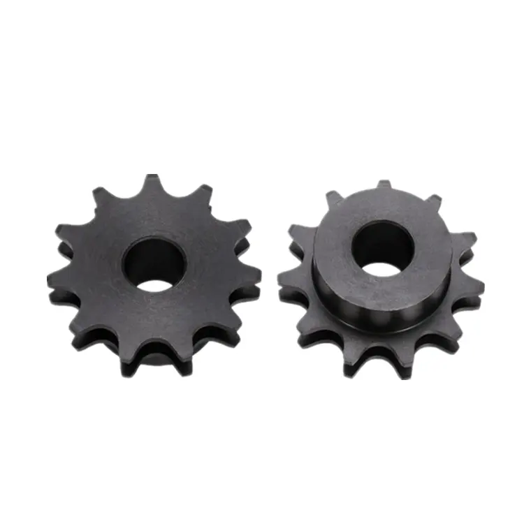
China Hot selling CNC Machining Part OEM Stainless Steel Motorcycle Part Chain Wheel Conveyor Sprocket Motorcycle Engine 219 Sprocket
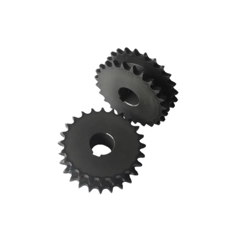
Product Description
CNC Machining Part OEM Stainless Steel Motorcycle Part Chain Wheel Conveyor Sprocket Motorcycle Engine 219 Sprocket
| We Are Professional Metal Processing Factory With Modern Automation Equipment, Specialized in Precision Machining part /Turning part /Welding part /Precision Fixture.Send Us RFQ Now, We will Feedback You Quotation Within 24 Hours. |
Product Description
| Equipment |
| 3-axis, 4-axis and full 5-axis processing equipment, CNC lathe, centering machine, turning and milling compound, wire cutting, EDM, grinding, etc |
| Processing |
| CNC machining, CNC Turning, CNC Milling, Welding, Laser Cutting, Bending, Spinning, Wire Cutting, Stamping, Electric Discharge Machining (EDM), Injection Molding |
| Materials |
| Aluminum:2000 series, 6000 series, 7075, 5052, etc. |
| Stainless steel: SUS303, SUS304, SS316, SS316L, 17-4PH, etc. |
| Steel:1214L/1215/1045/4140/SCM440/40CrMo, etc. |
| Brass:260, C360, H59, H60, H62, H63, H65, H68, H70, Bronze, Copper |
| Titanium:Grade F1-F5 |
| Plastic:Acetal/POM/PA/Nylon/PC/PMMA/PVC/PU/Acrylic/ABS/PTFE/PEEK etc. |
| Tolerance |
| +/-0.002~+/-0.005mm |
| Our Advantages |
| 1)24 hours online service & Quickly Quote/Delivery. 2)100% QC quality inspection before delivery, and can provide quality inspection form. 3)10+ years of experience in the CNC machining area and have a senior design team to offer perfect modification suggestions |
| Quality Assurance |
| 100% Inspect Before Shipment, ISO9001:2015, ISO13485:2016, SGS, RoHs, TUV |
| Serface Treatment |
| Aluminum parts:Clear Anodized, Color Anodized, Sandblast Anodized, Chemical Film, Brushing, Polishing Stainless Steel parts:Polishing, Passivating, Sandblasting, Laser engraving, Electrophoresis black, Oxide black Steel parts:Zinc Plating, Oxide black, Nickel Plating, Chrome Plating, Carburized, Heat treatment Brass parts:Nickel Plating, chrome plating, Electrophoresis black, Oxide black, Powder coated |
Click Here Get Free Quotation
Machining Workshop
| Nonstander Gears Display |
| Strictly on Quality Contoul, 100% Inspect Before Shipment |
Click Here Get More Information
Packging And Delivery
Application Industry
| Areospace |
| Cylinder Heads, Turbochargers, Crankshafts, Connecting Rods Pistons, Bearing Caps, CV Joints, Steering Knuckles, Brake Calipers,Gears,Differential Housing, Axle Shafts |
| Robotics |
| Custom robotic end-effectors, Low-volume prototype, Pilot, Enclosures, Custom tooling, Fixturing |
| Medical Industry |
| Rotary Bearing Seal Rings for CZPT Knife,CT Scanner Frames,Mounting Brackets,Card Retainers for CT Scanners,Cooling Plenums for CT Scanners,Brackets for CT Scanners,Gearbox Components,Actuators,Large Shafts |
| Energy Industry |
| Drill Pipes and Casing, Impellers Casings, Pipe Control Valves, Shafts, Wellhead Equipment, Mud Pumps, Frac Pumps, Frac Tools,Rotor Shafts and disc |
| Auto&Motorcycle |
| Cylinder Heads, Turbochargers, Crankshafts, Connecting Rods Pistons,Bearing Caps, CV Joints, Steering Knuckles, Brake Calipers,Gears, Differential Housing, Axle Shafts |
| Home Appliances |
| Screws, hinges, handles, slides, turntables, pneumatic rods, guide rails, steel drawers |
Customer And Comment
More than 15 years of customer service experience in Japan, Europe and America, adapt to various technical standards (such as JIS in Japan, ASTM in America, DIN in Germany, etc. ), and it can provide a variety of materials processing and surface treatment.
Certifications
Click Here For RFQ
FAQ
Q1. What kind of production service do you provide?
CNC machining, CNC Turning, CNC Milling, Welding, Laser Cutting, Bending, Spinning, Wire Cutting, Stamping, Electric Discharge Machining (EDM), Injection Molding, Simple Assembly and Various Metal Surface Treatment.
Q2. How about the lead time?
Sample Production Time : Usually 5~10 Work Days
Mass Production Time : Usually 15~20 Work Days
Q3. How about your quality?
♦Our management and production executed strictly according to ISO9001 : 2008 quality System.
♦We will make the operation instruction once the sample is approval.
♦ We will 100% inspect the products before shipment.
♦If there is quality problem, we will supply the replacement by our shipping cost.
Q4. How long should we take for a quotation?
After receiving detail information we will quote within 24 hours
Q5. What is your quotation element?
Drawing or Sample, Material, finish and Quantity.
Q6. What is your payment term?
Mould : 50% prepaid, 50% after the mould finish, balance after sample approval.
Goods : 50% prepaid, balance T/T before shipment.
/* January 22, 2571 19:08:37 */!function(){function s(e,r){var a,o={};try{e&&e.split(“,”).forEach(function(e,t){e&&(a=e.match(/(.*?):(.*)$/))&&1
| Standard Or Nonstandard: | Nonstandard |
|---|---|
| Application: | Motor, Electric Cars, Motorcycle, Machinery, Marine, Toy, Agricultural Machinery, Aerospace/ Marine/Automotive/Medical Equipments |
| Hardness: | Hardened Tooth Surface |
| Manufacturing Method: | Cut Gear |
| Toothed Portion Shape: | Spur Gear |
| Material: | Stainless Steel |
| Samples: |
US$ 0.8/Piece
1 Piece(Min.Order) | |
|---|
| Customization: |
Available
| Customized Request |
|---|
wheel sprocket System in Heavy Machinery and Industrial Equipment
Yes, a wheel sprocket system is commonly used in heavy machinery and industrial equipment for power transmission and motion control. The wheel sprocket configuration is a versatile and efficient method of transmitting rotational force between two shafts.
In heavy machinery and industrial equipment, the wheel is typically attached to one shaft, while the sprocket is mounted on another shaft. A chain or a toothed belt is wrapped around the wheel sprocket, connecting them. When the wheel is rotated, the chain or belt engages with the sprocket, causing the sprocket and the connected shaft to rotate as well. This mechanism allows the transfer of power from one shaft to the other, enabling various components and parts of the machinery to function.
Common applications of the wheel sprocket system in heavy machinery include:
- Construction Machinery: Wheel loaders, excavators, cranes, and other construction equipment often use wheel sprocket systems for efficient power transmission in various moving parts.
- Material Handling Equipment: Forklifts, conveyor systems, and other material handling equipment utilize wheel sprocket configurations to move goods and materials smoothly and reliably.
- Mining Equipment: Mining machinery, such as drilling rigs and conveyors, often incorporate wheel sprocket assemblies for power transmission in challenging environments.
- Agricultural Machinery: Tractors, combines, and other agricultural equipment use wheel sprocket systems to drive various components like wheels and harvesting mechanisms.
- Industrial Robotics: Robots and automated systems in manufacturing often utilize wheel sprocket setups for precise motion control and efficient power transmission.
One of the key advantages of the wheel sprocket system is its ability to handle heavy loads and transmit power over long distances. It is a reliable and cost-effective method of power transmission in various industrial settings. However, proper maintenance and alignment are crucial to ensuring the system’s optimal performance and longevity.
Overall, the wheel sprocket system is a widely used and effective power transmission solution in heavy machinery and industrial equipment, offering versatility and efficiency in a range of applications.
Load-Carrying Capacities of wheel sprocket Combinations
The load-carrying capacity of a wheel sprocket assembly depends on various factors, including the material, size, and design of both the wheel sprocket. Here are some common types of wheel sprocket combinations and their load-carrying capacities:
- Steel Wheel with Steel Sprocket: This combination offers high load-carrying capacity and is commonly used in heavy-duty applications. Steel wheels can handle substantial loads, and when paired with steel sprockets, the assembly can withstand even higher forces.
- Nylon Wheel with Steel Sprocket: Nylon wheels are known for their lightweight and durable nature. When combined with steel sprockets, they provide a good load-carrying capacity while reducing the overall weight of the assembly.
- Polyurethane Wheel with Steel Sprocket: Polyurethane wheels offer excellent wear resistance and are suitable for medium to heavy loads. When paired with steel sprockets, this combination can handle moderate to high load capacities.
- Rubber Wheel with Cast Iron Sprocket: Rubber wheels are known for their shock-absorbing properties and are often used in applications requiring vibration dampening. When used with cast iron sprockets, this combination can handle medium loads.
- Plastic Wheel with Plastic Sprocket: This combination is suitable for light-duty applications where lower loads are expected. Plastic wheels and sprockets are often used in applications that require low friction and quiet operation.
- Custom wheel sprocket Combinations: In some cases, custom wheel sprocket combinations are designed to meet specific load-carrying requirements. These combinations can be tailored to suit the application’s unique demands.
It’s important to note that load-carrying capacities also depend on other factors, such as the type of bearing used in the wheel, the shaft material, and the overall design of the mechanical system. Engineers should carefully consider the intended application, operating conditions, and safety factors when selecting the appropriate wheel sprocket combination to ensure optimal performance and longevity of the system.
Calculating Gear Ratio for a wheel sprocket Setup
In a wheel sprocket system, the gear ratio represents the relationship between the number of teeth on the sprocket and the number of teeth on the wheel. The gear ratio determines the speed and torque relationship between the two components. To calculate the gear ratio, use the following formula:
Gear Ratio = Number of Teeth on Sprocket ÷ Number of Teeth on Wheel
For example, if the sprocket has 20 teeth and the wheel has 60 teeth, the gear ratio would be:
Gear Ratio = 20 ÷ 60 = 1/3
The gear ratio can also be expressed as a decimal or percentage. In the above example, the gear ratio can be expressed as 0.3333 or 33.33%.
It’s important to note that the gear ratio affects the rotational speed and torque of the wheel sprocket. A gear ratio greater than 1 indicates that the sprocket’s speed is higher than the wheel’s speed, resulting in increased rotational speed and reduced torque at the wheel. Conversely, a gear ratio less than 1 indicates that the sprocket’s speed is lower than the wheel’s speed, resulting in decreased rotational speed and increased torque at the wheel.
The gear ratio is crucial in various applications where precise control of speed and torque is required, such as bicycles, automobiles, and industrial machinery.
editor by CX 2024-03-08
China wholesaler 16b-1 Z17 Carbon Steel CZPT Conveyor Roller Chain Sprocket
Product Description
Specification
Applications
Company Profile
HangZhou Terry Machinery Co.Ltd is a leading supplier of bearings, Linear motion system for CNC , Ball transfer Unit and transmission component .the
growing industrial and Favorable policy of HangZhou benefit the development of Terry Machinery .Our products are utilized in industrial, motorcycle, vehicle
and Automation applications. Now we are exporting to 46 countries. including USA, GBR , Germany , Spain, Poland ,Turkey ect .The Goal of Terry Machinery
to provide out customers with widest range of products at competitive prices, backed with the best Service.OUR ADVANTAGE Products Our major products & Supplied:Meet all the international standards and ISO9001 -TS1694 Certificate Big volume in Stock, No MOQ required Personnel Our salespersons are well
trained to accommodate your requests and speak English for your conveniences.Our technicians and engineers Experience in the Industry area exceeds 23
years Service &Quality control ,We supply detailed drawings and offer when ever necessary,We help all customers promote and improve their sales.We inspect
every piece of products by ourselves before delivery.
Customer’s Review
Packing &Delivery
FAQ
/* March 10, 2571 17:59:20 */!function(){function s(e,r){var a,o={};try{e&&e.split(“,”).forEach(function(e,t){e&&(a=e.match(/(.*?):(.*)$/))&&1
| Standard Or Nonstandard: | Nonstandard |
|---|---|
| Application: | Machinery |
| Hardness: | Hardened Tooth Surface |
| Manufacturing Method: | Cast Gear |
| Toothed Portion Shape: | Spur Gear |
| Material: | Carbon Steel |
| Samples: |
US$ 7/Piece
1 Piece(Min.Order) | |
|---|
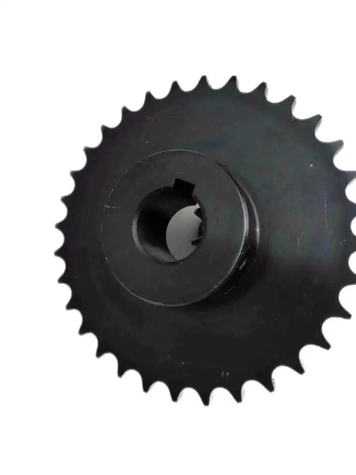
Calculating Torque Requirements for a wheel sprocket Assembly
Calculating the torque requirements for a wheel sprocket assembly involves considering various factors that contribute to the torque load. The torque requirement is crucial for selecting the appropriate motor or power source to drive the system effectively. Here’s a step-by-step guide:
- 1. Determine the Load Torque: Identify the torque required to overcome the resistance or load in the system. This includes the torque needed to move the load, overcome friction, and accelerate the load if applicable.
- 2. Identify the Sprocket Radius: Measure the radius of the sprocket (distance from the center of the sprocket to the point of contact with the chain or belt).
- 3. Calculate the Tension in the Chain or Belt: If using a chain or belt drive, calculate the tension in the chain or belt. Tension affects the torque required for power transmission.
- 4. Account for Efficiency Losses: Consider the efficiency of the system. Not all the input power will be converted into output power due to friction and other losses. Account for this efficiency in your calculations.
- 5. Use the Torque Equation: The torque (T) can be calculated using the following equation:
T = (Load Torque × Sprocket Radius) ÷ (Efficiency × Tension)
It’s essential to use consistent units of measurement (e.g., Newton meters or foot-pounds) for all values in the equation.
Remember that real-world conditions may vary, and it’s advisable to add a safety factor to your calculated torque requirements to ensure the system can handle unexpected peak loads or variations in operating conditions.
Using wheel sprocket Assembly in Robotics and Automation
Yes, wheel sprocket assemblies are commonly used in robotics and automation systems to transmit power and facilitate movement. These systems offer several advantages for robotic applications:
- Efficiency: wheel sprocket assemblies provide efficient power transmission, ensuring smooth and precise movement of robotic components.
- Compact Design: The compact nature of sprockets and wheels allows for space-saving designs, making them ideal for robotic applications where space is limited.
- Precision: Sprockets and wheels with accurate teeth profiles provide precise motion control, crucial for robotics and automation tasks that require high levels of accuracy.
- Low Noise: Properly lubricated and maintained wheel sprocket systems generate minimal noise during operation, contributing to quieter robotic movements.
- Customizability: wheel sprocket assemblies can be customized to suit specific robotic requirements, such as different gear ratios, sizes, and materials.
- Multiple Configurations: Depending on the robotic application, different configurations like single or multiple sprockets, idler sprockets, or rack and pinion systems can be used.
- High Load Capacity: Sprockets made from durable materials like steel can handle substantial loads, making them suitable for heavy-duty robotic tasks.
Examples of robotics and automation systems that commonly use wheel sprocket assemblies include:
- Robotic Arms: wheel sprocket systems are utilized in robotic arms to control their movement and reach.
- Automated Guided Vehicles (AGVs): AGVs use wheel sprocket assemblies for propulsion and steering, enabling them to navigate autonomously.
- Conveyor Systems: In automated factories, conveyor belts are often driven by sprockets and wheels for efficient material handling.
- Mobile Robots: Wheeled mobile robots use wheel sprocket assemblies to drive their wheels, enabling them to move in various directions.
- Robot Grippers: wheel sprocket mechanisms can be integrated into robot grippers to facilitate gripping and handling objects.
The choice to use wheel sprocket assemblies in robotics and automation depends on the specific application requirements, load capacity, precision, and environmental conditions. By selecting the appropriate sprockets, wheels, and materials, engineers can ensure reliable and efficient robotic performance in a wide range of automated tasks.
Working Principle of a wheel sprocket System
In a wheel sprocket system, the sprocket is a toothed wheel that meshes with a chain or a belt to transmit rotational motion and power from one component to another. The working principle can be explained in the following steps:
1. Power Input:
The system begins with a power input source, such as an electric motor or an engine, that generates rotational motion or torque.
2. Sprocket and Chain/Belt:
The power is transferred to the sprocket, which is mounted on a shaft. The sprocket has teeth that fit into the gaps of the chain or engage with the teeth of the belt.
3. Chain/Belt Movement:
As the sprocket rotates, it pulls the chain or belt along with it due to the engagement between the teeth. This movement is transmitted to the connected component, which could be another sprocket, a wheel, or any other part of the machinery.
4. Power Output:
The rotational motion or power is then delivered to the connected component, which performs a specific function depending on the application. For example, the power could be used to drive a conveyor belt, rotate the wheels of a vehicle, or operate various industrial machines.
5. Speed and Torque:
The size of the sprocket and the number of teeth, along with the size of the chain or belt, determine the speed and torque ratio between the input and output components. Changing the size of the sprocket or using different-sized sprockets in the system can alter the speed and torque characteristics of the machinery.
6. Efficiency and Maintenance:
Efficient power transmission relies on proper alignment and tension of the chain or belt with the sprocket. Regular maintenance, such as lubrication and inspection, is essential to ensure smooth operation and prevent premature wear or damage to the system.
The wheel sprocket system is widely used in various applications, including bicycles, motorcycles, industrial machinery, agricultural equipment, and more, where efficient power transmission and motion control are required.
editor by CX 2024-01-10
China factory Standard Conveyor Chain Sprockets or Chain Wheel Sprocket Hub
Product Description
Sprockets for Drop Forged Chains
| Chain Model |
Pitch (mm) |
Gear Number Z |
D2 (mm) |
D (mm) |
D3 (mm) |
D1 (mm) |
D4 (mm) |
A (mm) |
Number of Bolts |
Bolt Size |
B (mm) |
C (mm) |
| P100 | 100 | 6 | 197.8 | 70 | 105 | 143 | 135 | 83 | 6 | M12 | 16 | 36 |
| 100 | 7 | 228.2 | 70 | 108 | 146 | 173 | 83 | 6 | M12 | 16 | 36 | |
| 100 | 8 | 259.1 | 85 | 144 | 170 | 196 | 83 | 6 | M12 | 16 | 36 | |
| 100 | 9 | 290.4 | 105 | 174 | 200 | 232 | 83 | 6 | M12 | 16 | 36 | |
| 100 | 10 | 321.9 | 105 | 179 | 241.3 | 264 | 83 | 8 | M12 | 16 | 36 | |
| P142 | 142 | 6 | 284 | 85 | 136.5 | 168.3 | 190.5 | 112 | 6 | M12 | 16 | 46 |
| 142 | 7 | 327.3 | 105 | 162 | 200 | 234 | 112 | 6 | M16 | 16 | 46 | |
| 142 | 8 | 371.1 | 115 | 187.3 | 241.3 | 282 | 127 | 8 | M20 | 16 | 46 | |
| 142 | 9 | 415.2 | 150 | 240 | 285.8 | 330 | 127 | 8 | M20 | 16 | 46 | |
| 142 | 10 | 459.5 | 150 | 240 | 285.8 | 330 | 127 | 8 | M20 | 16 | 46 | |
| 142 | 11 | 504 | 170 | 310 | 368.3 | 419 | 150 | 8 | M20 | 16 | 46 | |
| 142 | 12 | 548.6 | 170 | 345 | 415 | 465 | 150 | 8 | M20 | 16 | 46 | |
| 142 | 13 | 593.4 | 170 | 380 | 470 | 521 | 150 | 8 | M20 | 16 | 46 | |
| 142 | 14 | 638.1 | 170 | 380 | 470 | 546 | 150 | 10 | M20 | 16 | 46 | |
| P142H | 142 | 7 | 327.3 | 105 | 162 | 200 | 234 | 127 | 6 | M16 | 18 | 69 |
| 142 | 8 | 371.1 | 115 | 187.3 | 241.3 | 282 | 150 | 8 | M20 | 18 | 69 | |
| 142 | 9 | 415.2 | 150 | 240 | 285.8 | 330 | 150 | 8 | M20 | 18 | 69 | |
| 142 | 10 | 459.5 | 150 | 240 | 285.8 | 330 | 150 | 8 | M20 | 18 | 69 | |
| 142 | 11 | 504 | 170 | 310 | 368.3 | 419 | 150 | 8 | M20 | 18 | 69 | |
| 142 | 12 | 548.6 | 170 | 345 | 415 | 465 | 150 | 8 | M20 | 18 | 69 | |
| 142 | 13 | 593.4 | 170 | 380 | 470 | 520 | 180 | 8 | M20 | 18 | 69 | |
| 142 | 14 | 638.1 | 170 | 380 | 470 | 546 | 180 | 10 | M20 | 18 | 69 |
Trailers for Drop Forged Chains
| Chain Model | Gear Number Z |
D1 (mm) |
D (mm) |
A (mm) |
C (mm) |
| P100 | 6 | 197.8 | 65 | 57 | 35 |
| 7 | 228.2 | 65 | 57 | 35 | |
| 8 | 259.1 | 65 | 57 | 35 | |
| 9 | 290.4 | 65 | 57 | 35 | |
| 10 | 321.9 | 65 | 57 | 35 | |
| P142 | 6 | 284 | 85 | 74 | 45 |
| 7 | 327.3 | 85 | 74 | 45 | |
| 8 | 371.1 | 85 | 77 | 45 | |
| 9 | 415.2 | 115 | 77 | 45 | |
| 10 | 459.5 | 115 | 77 | 45 | |
| 11 | 504 | 115 | 105 | 45 | |
| 12 | 548.6 | 115 | 105 | 45 | |
| 13 | 593.4 | 115 | 120 | 45 | |
| 14 | 638.1 | 115 | 120 | 45 | |
| P142H | 7 | 327.3 | 115 | 110 | 75 |
| 8 | 371.1 | 115 | 110 | 75 | |
| 9 | 415.2 | 115 | 110 | 75 | |
| 10 | 459.5 | 115 | 120 | 75 | |
| 11 | 504 | 140 | 120 | 75 | |
| 12 | 548.6 | 140 | 120 | 75 | |
| 13 | 593.4 | 140 | 120 | 75 | |
| 14 | 638.1 | 140 | 140 | 75 |
Note: Customized sizes and material are available CZPT request
Sprockets for Roller Conveyor Chains
| Model | Pitch(mm) | Gear Number Z |
d1 (mm) |
d (mm) |
D (mm) |
D1 (mm) |
A (mm) |
B (mm) |
| 66.675 | 66.675 | 6 | 22.23 | 133.41 | 40 | 75 | 80 | 22.8 |
| 66.675 | 7 | 22.23 | 153.74 | 40 | 75 | 80 | 22.8 | |
| 66.675 | 8 | 22.23 | 174.31 | 50 | 100 | 100 | 22.8 | |
| 66.675 | 9 | 22.23 | 195.04 | 50 | 100 | 100 | 22.8 | |
| 66.675 | 10 | 22.23 | 215.87 | 60 | 110 | 100 | 22.8 | |
| 66.675 | 11 | 22.23 | 236.78 | 60 | 110 | 100 | 22.8 | |
| 66.675 | 12 | 22.23 | 257.74 | 60 | 110 | 100 | 22.8 | |
| 100 | 100 | 8 | 36 | 261.44 | 60 | 110 | 100 | 33.2 |
| 100 | 9 | 36 | 292.52 | 70 | 120 | 100 | 33.2 | |
| 100 | 10 | 36 | 323.77 | 70 | 120 | 100 | 33.2 |
Tht
The full range of our conveyor products:
/* March 10, 2571 17:59:20 */!function(){function s(e,r){var a,o={};try{e&&e.split(“,”).forEach(function(e,t){e&&(a=e.match(/(.*?):(.*)$/))&&1
| Transport Package: | Pallet |
|---|---|
| Specification: | Drop Forged Chain Sprockets, Roller Chain Sprocket |
| Trademark: | Yutung |
| Origin: | China |
| Samples: |
US$ 10/Piece
1 Piece(Min.Order) | |
|---|
| Customization: |
Available
| Customized Request |
|---|
Alternatives to Chain Sprockets in wheel sprocket Configuration
While chain sprockets are commonly used in wheel sprocket configurations, there are alternative methods for power transmission in various applications:
- Gear and Gear Rack: Gears are toothed wheels that mesh with each other to transmit power. Instead of using a chain and sprocket, gears can directly engage with each other, offering a smooth and efficient power transfer. Gear racks, which are linear gears, can be used in place of wheels for linear motion applications.
- Belt and Pulley: Belts and pulleys offer a flexible and quiet means of power transmission. They work similarly to chain and sprocket systems but use belts instead of chains. Pulleys have grooves that grip the belt, allowing power to be transferred between the pulleys.
- Gear Train: A gear train consists of multiple gears meshed together to achieve specific speed and torque ratios. Gear trains are often used in complex machinery and mechanical systems where precise power transmission is required.
- Direct Drive: In some applications, direct drive mechanisms can be used, where the motor or power source is directly connected to the wheel or load without any intermediate components like sprockets or gears.
- Friction Drive: Friction drive systems use the friction between two surfaces to transfer power. One surface, such as a rubber wheel, is pressed against another surface to achieve power transmission.
The choice of alternative power transmission methods depends on various factors, including the application requirements, available space, speed, torque, and efficiency considerations. Each alternative method has its advantages and limitations, and the selection should be based on the specific needs of the mechanical system.
When considering alternatives to chain sprockets, it is essential to analyze the requirements of your application and consult with engineering experts or manufacturers to determine the most suitable method of power transmission for optimal performance and longevity.
Using a Belt Sprocket in Place of a Chain Sprocket with a Wheel
Yes, in many cases, a belt sprocket can be used in place of a chain sprocket with a wheel, provided that the system is designed to accommodate the change.
Both chain sprockets and belt sprockets serve the same fundamental purpose of transferring rotational motion and power between the wheel and the driven component. However, there are some important considerations to keep in mind when replacing a chain sprocket with a belt sprocket:
- Alignment: Belt sprockets and chain sprockets must be aligned properly with the wheel to ensure smooth and efficient power transmission. Any misalignment can cause premature wear and reduce the system’s overall performance.
- Tension: Chain-driven systems require specific tension to prevent slack and maintain proper engagement between the sprockets and the chain. Belt-driven systems, on the other hand, require appropriate tension to prevent slippage. Ensuring the correct tension for the specific type of sprocket is crucial for reliable operation.
- Load Capacity: Consider the load capacity and torque requirements of the system when selecting a belt sprocket. Belt sprockets may have different load-carrying capabilities compared to chain sprockets, and using the wrong type can lead to premature wear or failure.
- Speed and RPM: Belt-driven systems may have different operating speeds and RPM limits compared to chain-driven systems. Ensure that the selected belt sprocket can handle the desired rotational speed without exceeding its design limitations.
- System Design: Changing from a chain-driven system to a belt-driven system (or vice versa) may require modifications to the overall system design, including the size of the sprockets and the layout of the system. Consult with an engineer or a qualified professional to ensure that the replacement is appropriate and safe.
Overall, replacing a chain sprocket with a belt sprocket can be a viable option in certain applications. However, it’s essential to consider the factors mentioned above and evaluate the compatibility of the new sprocket with the existing system to achieve optimal performance and longevity.
Calculating Gear Ratio for a wheel sprocket Setup
In a wheel sprocket system, the gear ratio represents the relationship between the number of teeth on the sprocket and the number of teeth on the wheel. The gear ratio determines the speed and torque relationship between the two components. To calculate the gear ratio, use the following formula:
Gear Ratio = Number of Teeth on Sprocket ÷ Number of Teeth on Wheel
For example, if the sprocket has 20 teeth and the wheel has 60 teeth, the gear ratio would be:
Gear Ratio = 20 ÷ 60 = 1/3
The gear ratio can also be expressed as a decimal or percentage. In the above example, the gear ratio can be expressed as 0.3333 or 33.33%.
It’s important to note that the gear ratio affects the rotational speed and torque of the wheel sprocket. A gear ratio greater than 1 indicates that the sprocket’s speed is higher than the wheel’s speed, resulting in increased rotational speed and reduced torque at the wheel. Conversely, a gear ratio less than 1 indicates that the sprocket’s speed is lower than the wheel’s speed, resulting in decreased rotational speed and increased torque at the wheel.
The gear ratio is crucial in various applications where precise control of speed and torque is required, such as bicycles, automobiles, and industrial machinery.
editor by CX 2023-12-28